The condenser and evaporator assemblies of a Khodro Bus Air Conditioner are typically separate from the electric compressor and inverter power supply. This is a common situation.
The former is installed on the roof, while the latter is installed below the bus.
This setup takes up a lot of space in the bus cabin.
Furthermore, this setup requires connecting the compressor, condenser, and evaporator assemblies with piping and charging refrigerant only at the bus manufacturing site.
The connecting piping is approximately ten meters long, resulting in low heat exchange efficiency and high energy consumption.
Conserving materials and energy is a major trend, and therefore the bus market urgently needs new air conditioning products.
Utility Model Content
The fully roof-mounted Khodro Bus Air Conditioner features a compact and rational structure, occupies minimal roof space, and reduces costs and energy consumption.
The technical solution employed by the Bus Air Conditioner to solve its technical problems is as follows:
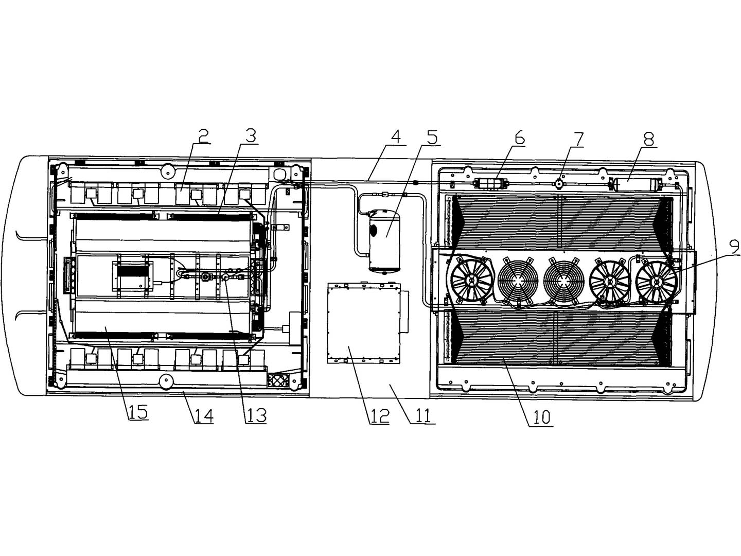
It comprises an air conditioner housing, a condenser core, a condenser fan, an evaporator core, an evaporator fan, a compressor, a power supply, and an electrical control unit. The evaporator core is located at one end of the air conditioner housing, the condenser core is located at the other end, and the compressor and power supply are located in the middle of the housing.
A PTC electric heater and evaporator fan are installed outside the evaporator core, while the condenser fan is located in the middle of the condenser core.
The compressor is connected to the condenser core, which in turn is connected to the evaporator core, and the evaporator core is connected to the compressor, forming a circulation system.
The pipes connecting the condenser core and the evaporator core are sequentially connected with a receiver-dryer and an expansion valve. The receiver-dryer comprises a receiver and a dryer, with a shutoff valve located between the receiver and the dryer.
1. Air conditioner housing, 2. Evaporator fan, 3. PTC electric heater, 4. Piping, 5. Compressor, 6. Dryer, 7. Shutoff valve, 8. Receiver, 9. Condenser fan, 10. Condenser core, 11. Intermediate chamber, 12. Power supply, 13. Expansion valve, 14. Evaporator chamber, 15. Evaporator core. Bus Air Conditioner offers the following significant advantages:
All components are located on the vehicle roof, resulting in a compact and rational structure, minimizing roof space, reducing costs and energy consumption, and improving system performance.
The evaporator fan 2, condenser fan 9, and electrical control unit are driven by a low-voltage DC power supply.
The compressor 5 is driven by an AC power supply.
Both the low-voltage DC and AC power supplies are converted from the high-voltage DC power of the electric bus.
The evaporator core 15 is located within the evaporator chamber 14.
The compressor 5 and power supply 12 are located within the intermediate chamber 11 of the air conditioner casing 1.
The intermediate chamber 11 serves as a heat sink, dissipating heat from the power supply 12.
The compressor 5 draws in low-temperature, low-pressure gaseous refrigerant at the outlet of the evaporator core 15, compresses it into high-temperature, high-pressure gas, and discharges it from the compressor 5.
The high-temperature, high-pressure superheated gaseous refrigerant enters the condenser core 10 via pipeline 4, where it is cooled by the forced airflow generated by the vehicle's forward motion. The refrigerant condenses from gas to supercooled liquid, releasing a large amount of heat energy into the atmosphere.